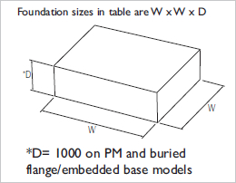
The table below shows foundation sizes for area D installations and, for exposed, elevated locations, higher than 100-150m above sea level. For areas A,B and C the left hand column shows the foundation size shown in the product foundation page - read across the table for the relevant foundation size to be used for the relevant location.
e.g. in the relevant foundations table an ACC2/BPLA for country location in area B has a foundations size of 1.2 x 1.2 x 0.6 but the location is at 300m ASL. Look for the foundation size in the left hand column of the table below and read across the row to the 'Elevated foundation' column for the correct foundation size, for the elevated
location.
- For locations above 350m above sea level (ASL) and area D locations above 250m ASL, please contact Altron who will advise on product suitability and foundation sizes.
- Products marked with an asterisk in their foundation page are note suitable for installations in Area D or in area C above 200m. Please select an alternative product.
| Foundation size Shown in product Foundations table Area A&B 0-100m Area C 0-150m |
Area D foundation size to be used (0-250m ASL) instead of area C foundation |
Area A&B foundation sizes for elevated sites 100-200mASL |
Area A&B foundation sizes for elevated sites 200-350m ASL |
Area C foundation sizes for elevated sites 150-350mASL |
| 0.8 x 0.8 x 0.4 | 0.9 x 09 x 0.5 | 0.9 x 09 x 0.5 | 1.0 x 1.0 x 0.5 | 0.9 x 09 x 0.5 |
| 0.9 x 0.9 x 0.5 | 1.0 x 1.0 x 0.5 | 1.0 x 1.0 x 0.5 | 1.1 x 1.1 x 0.55 | 1.0 x 1.0 x 0.5 |
| 1.0 x 1.0 x 0.5 | 1.1 x 1.1 x 0.55 | 1.1 x 1.1 x 0.55 | 1.2 x 1.2 x 0.6 | 1.1 x 1.1 x 0.55 |
| 1.1 x 1.1 x 0.55 | 1.2 x 1.2 x 0.6 | 1.2 x 1.2 x 0.6 | 1.3 x 1.3 x 0.65 | 1.2 x 1.2 x 0.6 |
| 1.2 x 1.2 x 0.6 | 1.3 x 1.3 x 0.65 | 1.3 x 1.3 x 0.65 | 1.4 x 1.4 x 0.7 | 1.3 x 1.3 x 0.65 |
| 1.3 x 1.3 x 0.65 | 1.4 x 1.4 x 0.7 | 1.4 x 1.4 x 0.7 | 1.5 x 1.5 x 0.75 | 1.4 x 1.4 x 0.7 |
| 1.4 x 1.4 x 0.7 | 1.5 x 1.5 x 0.75 | 1.5 x 1.5 x 0.75 | 1.6 x 1.6 x 0.8 | 1.5 x 1.5 x 0.75 |
| 1.4 x 1.4 x 0.75 | 1.5 x 1.5 x 0.75 | 1.5 x 1.5 x 0.75 | 1.6 x 1.6 x 0.8 | 1.5 x 1.5 x 0.75 |
| 1.5 x 1.5 x 0.75 | 1.6 x 1.6 x 0.8 | 1.6 x 1.6 x 0.8 | 1.7 x 1.7 x 0.9 | 1.6 x 1.6 x 0.8 |
| 1.6 x 1.6 x 0.8 | 1.7 x 1.7 x 0.9 | 1.7 x 1.7 x 0.9 | 1.8 x 1.8 x 0.9 | 1.7 x 1.7 x 0.9 |
| 1.7 x 1.7 x 0.9 | 1.8 x 1.8 x 0.9 | 1.8 x 1.8 x 0.9 | 1.9 x 1.9 x 1.0 | 1.8 x 1.8 x 0.9 |
| 1.8 x 1.8 x 0.9 | 1.9 x 1.9 x 1.0 | 1.9 x 1.9 x 1.0 | 2.0 x 2.0 x 1.0 | 1.9 x 1.9 x 1.0 |
| 1.9 x 1.9 x 1.0 | 2.0 x 2.0 x 1.0 | 2.0 x 2.0 x 1.0 | 2.1 x 2.1 x 1.1 | 2.0 x 2.0 x 1.0 |
| 2.0 x 2.0 x 1.0 | 2.1 x 2.1 x 1.1 | 2.1 x 2.1 x 1.1 | 2.2 x 2.2 x 1.1 | 2.1 x 2.1 x 1.1 |
| 2.1 x 2.1 x 1.1 | 2.2 x 2.2 x 1.1 | 2.2 x 2.2 x 1.1 | 2.3 x 2.3 x 1.2 | 2.2 x 2.2 x 1.1 |
| 2.2 x 2.2 x 1.1 | 2.3 x 2.3 x 1.2 | 2.3 x 2.3 x 1.2 | 2.4 x 2.4 x 1.2 | 2.3 x 2.3 x 1.2 |
| 2.3 x 2.3 x 1.2 | 2.4 x 2.4 x 1.2 | 2.4 x 2.4 x 1.2 | 2.5 x 2.5 x 1.2 | 2.4 x 2.4 x 1.2 |
- Grade C28/35 concrete to be used
- Allow a minimum of 72 hours for concrete to cure before placing pole/column/tower.
- A minimum ground bearing capacity of 75 kN/m2 is assumed
- Foundations comply with BS EN 1997-1:2004, BS 8004, ILETR7
and PLG07 - Foundation sizes are based on foundations being founded on natural ground. For made up ground, further assessment on ground suitability may be required.
- Foundation sizes shown are suitable for maximum equipment load and wind surface area as shown in product technical tables. For greater
loads, foundations sizes will need to be increased, please contact us and
we will advise on product suitability for greater loads and foundation requirements. - Foundation sizes shown are not suitable for installations that include
PV/ solar panels or small wind turbines. For this type of installation.
The main factor that determines foundation size (other than the location of the installation), is the wind surface area of the equipment
being mounted on the pole/ tower/ column. It is the wind surface area that produces the wind force (kgf) that transfers itself to the
foundation, for which the foundation needs to be of sufficient size to overcome the 'over turning moment' produced by this lever force.
The greater the surface area of equipment at the top of the structure, the larger the foundation size required, so it is very important that the 'Max equip surface area' shown in our technical tables is not exceeded.An extreme example of this is a solar panel which can be very light - only a few kilograms, but can have a large surface area and therefore require a much larger foundation size than the ones we state.
Equipment Weight
The actual weight of the camera equipment does not significantly affect the foundation size, so for fixed, non-tilting products weight is not an issue.The weight of equipment is only relevant for tilt-down products, where the camera equipment weight needs to be lowered using the winch and winch cable.Weight then is then very important on tilt-down products, so as not to overload the winch and cable mechanism, so for tilt-down products the stated 'max equip weight' should not be exceeded.
Off-set Loads
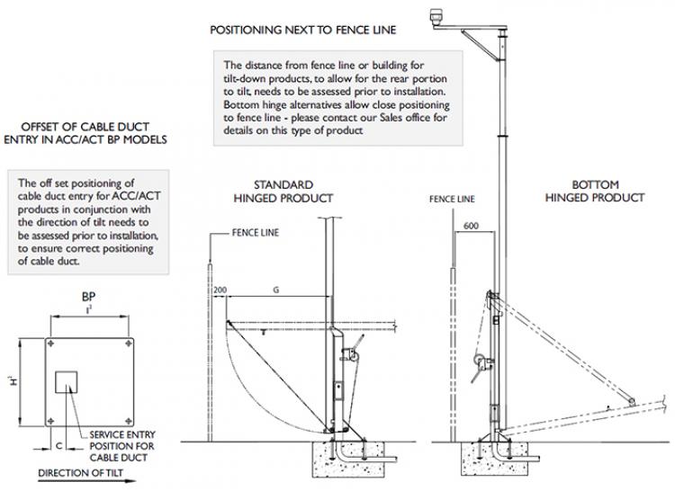
Off-set loads on fixed poles/ towers/ columns, typically produced by using one of our PMB or POB mounting brackets, are not a significant, other than the fact that an off-set load increases the deflection of the structure and the movement of the camera monitor image. Offset loads will also increase the stress on the structure, so even though most Altron poles, towers and columns have plenty of capacity for increased stress, some do not, so it is important to consult with us when anything more than a relatively small offset (600mm) is being used. Towers do not like to be twisted, so a pole is much better for an offset load then a tower, but a larger diameter pole will be needed to keep deflection to a minimum.
Extended offset loads on tilt-down products that are greater than 600mm are not so desirable, unless in line with the direction of tilt, or if they are balanced (an equal load either side so when tilting the product, it is balanced). If the extended off-set load is not balanced, then this produces a side load at the hinge point, which can cause the hinge to bind, increasing the load on the winch mechanism. We therefore recommend that an extended side load on a tilt-down product is only in line with the direction of tilt, or equal either side, so a balanced load.
Positioning Foundations
The following factors should be considered when assessing the location of a foundation in accordance with the type of product being used.
Site Specific Foundations
- Minimum foundation size provided
- Reduced installation cost
- Reduced foundation footprint for tight locations
We can specify a more accurate foundation size for specific site locations. Foundations sizes shown in product tables are for the max allowable head load and for the highest windspeed for the Area A,B,C or D (for instance, the centre of London has a mean wind speed of 22.05 m/s rather than the 24.2 m/s we use for area A in general). Given a specific site location and maximum equipment load that will be employed, we can provide an ideal foundation size that will be the minimum required for the site. This can save on civils costs and also help when there are site restrictions for foundation size.
Foundation Design Service
- Where ground conditions do not comply with our standard foundation designs
- Where services or other obstructions do not allow a standard foundation to be cast
- Where product loading exceeds our stated loading
- For non-standard product variations
- To comply with specific design standards
For all products,we can provide specific foundation designs, for site conditions that do not comply with our standard designs. We are happy to provide guidance and pricing on request.