Flange Plate
Flange Plate Installation Method
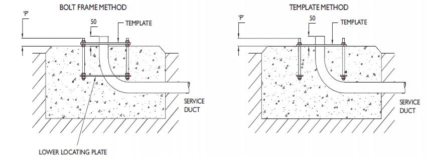
1. Excavate as per recommended area and depth.
2. Shutter off top edge level and place ducting - ensure that all shuttering is supported.
3.Assemble bolts through template and screw nuts on so that recommended thread is protruding through template to give the relevant 'P' dimension when bolts are set in foundation, as noted in table.
4. If using bolt frame, ensure that the nut below the top template will be clear of the finished concrete surface level when the 'P' dimension is achieved.
5. For bolt frame method, position the assembled bolt frame in place within foundation pit, using cross slats to bridge pit and position service ducting so that a minimum of 50mm of duct will be proud of the finished concrete surface level.
6. Pour concrete level with top of shuttering, tamp down and level surface.
7. For bolt frame method, use a vibrating poker whilst pouring concrete to ensure no air traps around bolt frame lower locating plate.
8. For template method, push bolts down into concrete so that template is flat on concrete and nuts are against template with bolts vertical. Ensure that cable duct end is through entry hole in template and protrudes by 50mm min.
9. Allow 72 hours for concrete to cure before placing pole/column
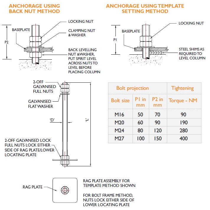
10. Remove template before placing pole. Note: Where back nuts are used to level pole/column it is essential that a load bearing grout is used to fill the void between base plate and concrete. Failure to do this may cause excessive deflection in pole.
Bolt Frames
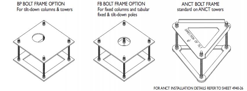
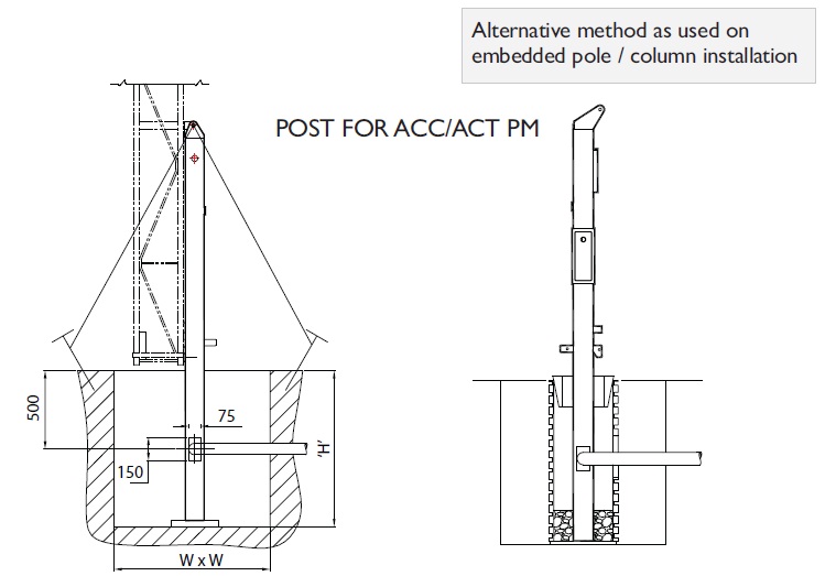
PM Method for columns and towers
1. Excavate as per recommended area and depth.
2. Shutter off top edge level and place ducting - ensure that all shuttering is supported.
3. Place 100mm of hardcore (paving slab) under post.
4. Guy from top of post with 3-4 stakes and guy ropes.
5. Plumb level post by adjusting guy ropes position ducting as required, ensuring it is supported sufficiently.
6. Pour concrete and check post for plumb.
7. Allow 72 hours for concrete to cure.
8. Remove guys and stakes.
9. Fix tower to post.
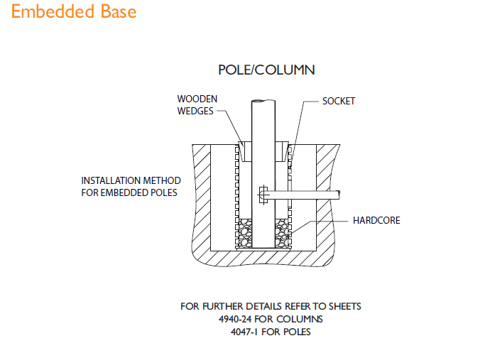
Embedded base installation method
1. Excavate as per recommended area and depth
2. Set socket into excavated pit on 2no 1 inch thick slabs or suitable hardcore
3. Ensure socket verticality and that it is supported centrally.
4. Position service duct so that 100mm enters the socket, ensuring correct orientation with service entry point on pole.
5. Pour concrete on the outside of the pipe and fill pit to just below the top level of the socket.
6. Allow to cure for minimum of 72 hours
7. Lower pole into socket and support in position for operations 8-11
8. Fill hardcore and sand around the base of the pole to a depth of approx 150mm
9. Pack this down so that it is well compressed
10. Select timber wedges and wedge pole in 3 places ensuring pole is vertical
11. For poles up to 7 metres in height pour concrete into open socket. For poles over 7 metres in height use a cementitious grout instead of concrete. Use a vibrating poker to ensure no voids or air traps.
12. Allow 72 hours to cure
13. Remove wedges and fill gaps with grout
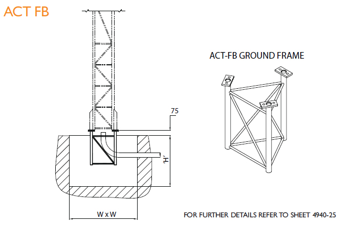
FB Method for towers
1. Excavate as per recommended area and depth.
2. Shutter off top edge level and place ducting - ensure that all shuttering is supported.
3. Support tower ground frame in excavated base by tying wooden slat across top of frame and resting end of slat either side of base.
4. Support slats in raised position so that top of tower ground frame is 75mm proud of base surface.
5. Position ducting so that it enters the base next to the required tower leg.
6. Level frame across the 3 No. flange ends.
7. Pour concrete and then check frame is level.
8. Allow 72 hours for concrete to cure before placing tower.
Alternative holding down methods
Installation of chemical anchors
For use on existing cast foundations or as an alternative to standard holding down bolts.
- We recommend the use of chemical anchors over expanding sheath type anchors.
- We can supply the chemical anchors shown below ex stock.
- For full details on chemical anchors and installation method please contact our Sales team.
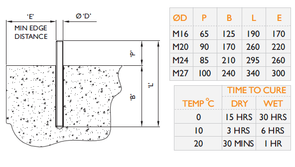
Installation method
1. Drill correct diameter and depth of hole for the stud.
2. Clean the hole using a brush and air pump.
3. Insert chemical capsule into the hole connect stud to drilling machine using an appropriate driver.
4. Offer stud to capsule and switch on machine. Drive stud into capsule to full depth.To prevent over mixing, stop rotation as soon as bottom of hole is reached. Leave undisturbed until resin has set.
5. Position baseplate and tighten to recommended torque. To ensure correct installation of chemical anchor bolts an experienced contractor should be employed.
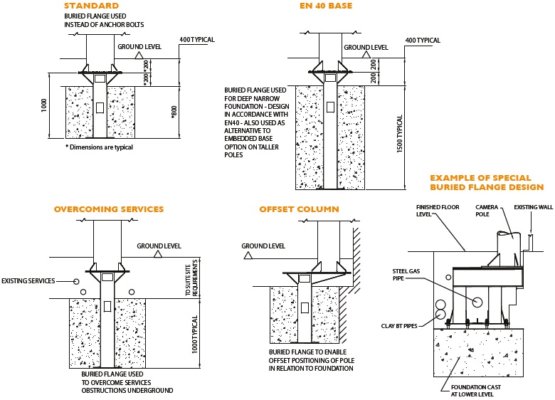
Buried flange members
Where underground services restrict the possible location of the foundation/ camera position, buried Flange Members
can often overcome congestion & provide a solution. Buried flange members can also be used as an alternative to other standard holding down methods and also to acheive installations typically outlined below, where other methods are not suitable.